Quadrature Phase Shift Keying: Difference between revisions
No edit summary |
m (merge QPSK) |
||
| (2 intermediate revisions by 2 users not shown) | |||
| Line 1: | Line 1: | ||
The '''Quadrature Phase Shift Keying''' or '''QPSK''' is a [[Modulation Scheme]] where the [[Phase]] of the modulated signal is shifted depending on the incoming bitstream by an angle of -135°, -45°, +45° or +135°. Thus 4 states (a two-digit binary symbol) can get expressed in every transition: |
|||
[[Image:Qpsk.jpg|QPSK Sample points in the Phase Plot]] |
[[Image:Qpsk.jpg|QPSK Sample points in the Phase Plot]] |
||
| Line 5: | Line 5: | ||
The resulting waveform looks like if it would be assembled of several sine wave segments from 4 phase-shifted base sine signals. |
The resulting waveform looks like if it would be assembled of several sine wave segments from 4 phase-shifted base sine signals. |
||
[[Image:Principle_QPSK.jpg|picture of a sine signal with shifted phase]] |
|||
In order to minimize the used [[Bandwidth]] allocated on the [[Transponder]] the outgoing signal is usually filtered using digital low-pass [[FIR Filter]]s with smooth roll-off so that the high-order noise of the sudden state changes gets removed. |
In order to minimize the used [[Bandwidth]] allocated on the [[Transponder]] the outgoing signal is usually filtered using digital low-pass [[FIR Filter]]s with smooth roll-off so that the high-order noise of the sudden state changes gets removed. |
||
| Line 15: | Line 15: | ||
''a few words about allocated bandwidth and noise sensitivity of QPSK modulated signals would be great.'' |
''a few words about allocated bandwidth and noise sensitivity of QPSK modulated signals would be great.'' |
||
[[Category:Technology]] |
|||
Latest revision as of 22:16, 2 April 2005
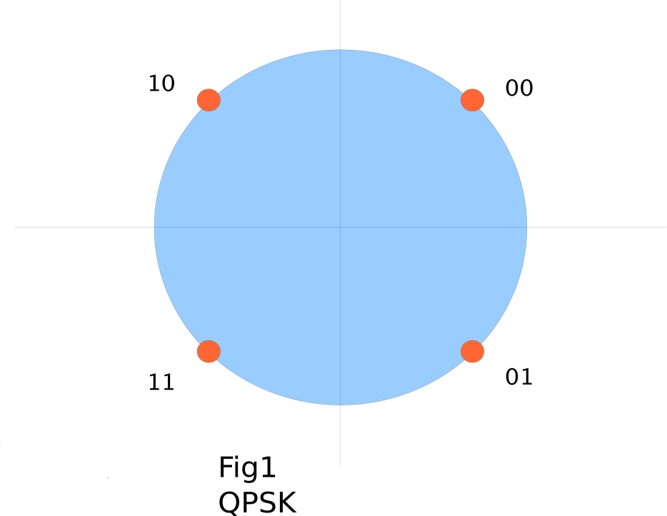
The Quadrature Phase Shift Keying or QPSK is a Modulation Scheme where the Phase of the modulated signal is shifted depending on the incoming bitstream by an angle of -135°, -45°, +45° or +135°. Thus 4 states (a two-digit binary symbol) can get expressed in every transition:
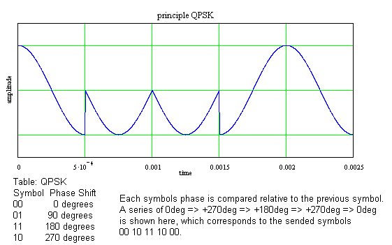
The resulting waveform looks like if it would be assembled of several sine wave segments from 4 phase-shifted base sine signals.
In order to minimize the used Bandwidth allocated on the Transponder the outgoing signal is usually filtered using digital low-pass FIR Filters with smooth roll-off so that the high-order noise of the sudden state changes gets removed.
here we may show the smoothed version of the sine sigal with shifted phase. Maybe also the spectrum diagrams?
Has anybody the standard number of the paper that specifies usage of QPSK in DVB-S handy? Any more useful information in there?
a few words about allocated bandwidth and noise sensitivity of QPSK modulated signals would be great.

