Amplitude modulation: Difference between revisions
(corrected.) |
|||
| Line 7: | Line 7: | ||
==Mathematical Setting== |
==Mathematical Setting== |
||
[[Image:AM_mathematical_desc.jpg|Description]] |
|||
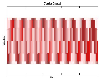
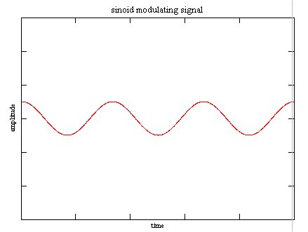
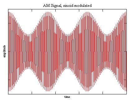
The first formula desribes what happens in time domain. It's basically multiplying of two cosine signals leading to the time domain picture in the example below. |
|||
The output signal is the simple product of incoming signal and Carrier Signal with frequency ''f'': |
|||
The second formula describes the frequency response, the frequency spectrum consists of three spectrum lines at each time t. The first term is the carrier, for shure the carrier is in the spectrum, the second and third termes describe two spectrum lines around the carrier, and their amplitude is dependend on the modulation index m. As the modulating sognakll variies the lines around the carrier frequency are variing. |
|||
''output(t) = input(t) * sin(f * t)'' |
|||
''TODO: it would be nice to type formulas in TeX, is this working in this wiki?'' |
|||
:''Sure. But some prerequisites has to be met. Perhaps ist easier to use pictures of the formula (the manual way of what the wiki does).'' |
|||
''we should add an frequeny response picture below in the example'' |
|||
==An Example== |
==An Example== |
||
Revision as of 19:56, 28 September 2004
What is AM?
Amplitude Modulation is the done by modulating the Amplitude of an sinoid Carrier signal using the incoming signal.
The Carrier signal is sinusoid with a fixed Frequency, usually much higher than the highest frequency occuring in the spectrum of the modulating signal. Amplitude Modulation schemes have been widely used in Analog Radio.
Mathematical Setting
The first formula desribes what happens in time domain. It's basically multiplying of two cosine signals leading to the time domain picture in the example below.
The second formula describes the frequency response, the frequency spectrum consists of three spectrum lines at each time t. The first term is the carrier, for shure the carrier is in the spectrum, the second and third termes describe two spectrum lines around the carrier, and their amplitude is dependend on the modulation index m. As the modulating sognakll variies the lines around the carrier frequency are variing.
we should add an frequeny response picture below in the example
An Example
File:AM picture4.jpg Carrier Signal in frequency domain (to be added) | |
File:AM picture5.jpg Modulating Signal in frequency domain (to be added) | |
File:AM picture6.jpg AM Signal in frequency domain (to be added) |
Special Kinds of AM
- DSSC, Double Sideband Supressed Carrier
- SSB, Single Side Band
- Residual Sideband Modulation (modulation used for analog TV applications)
- QAM, Quadrature Amplitude Modulation
Aquired Bandwidth
it would be nice to have a picture showing how AM signals in the frequency spectrum behave and how much bandwidth they allocate. A short overview of AM-related problems would be nice, too. Has anybody of you this info handy?
what about noise sensitivity?


