Shielded Loop Antenna / Yagi-Uda array of loops
It is plenty of article on home builds antenna onto the internet. Most of them are for antenna that can work for both emission and reception.
We will see here two different designs for reception into the FM and TV band. Those 2 designs are using the same base type of antenna: the loop antenna.
Shielded loop
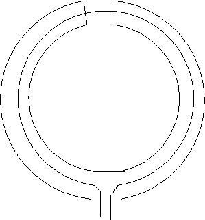
A crude representation of a shielded loop:

The principle is the same than for a loop. From wikipedia: a continuous conducting path leading from one conductor of a two-wire transmission line to the other conductor. All planar loops are directional antennas with a sharp null, and have a radiation pattern similar to the dipole antenna with E and H fields interchanged.
The main advantages of loops antenna are tree:
1) An outstanding signal quality. It is a simple design that perform very well.
2) For large loops, higher gain (about 10%) than the other forms.
3) Large loop antennas are less susceptible to localized noise, partly due to their lack of a need for a groundplane.
The advantage of a shielded loop over a non shielded one:
4) The electric interference from the big city (streetlights, television's , cars etc...) have no influence on the received signal.
Practical realization
Like we will not perform emission, any good quality coaxial cable may be used to realize such an antenna. Critical to correctly design this antenna is the wavelength of the program you want to receive best.
Less critical but important is the capacitance of the coaxial cable. The circumference of the loop will be equal to the wavelenght, and that capacitance is not negligible. In practice, any good coaxial cable for TV installation will do the job.
My first concern with this antenna was the FM band, because I was completely unable to receive my favorite radio program on 93.8 MHz where I am living.
Wavelength [meter] = 300 / frequency [MMHz]
For 93.8 MHz, we have 300 / 93.8 = 3.198 meters.
According to the Balanis (Antenna Theory: Analysis and Design, by Constantine A. Balanis, it is better to use a little bigger circle. (Read the book for the details.)
Antenna circumference = 1.1 * wavelength = 1.1 * 3.198 = 3.518 meters.
So, we need 3.52 meters of coaxial cable.
For the realization, it is up to you. Metal will not work because it will interfere with the antenna. Plastic or wood are best. The best design is one that will approach a perfect circle, like a bicycle wheel.
I made mine with one vertical stick of wood and 6 smaller sticks of the same wood. I made small holes at the extremity of each stick in order to be able to attach the coaxial there. I used 2 more little pieces of wood at the center of this wheel in order to fix the sticks.
We also need to cut 1 cm of the shield at the top of the antenna. The center wire must be left intact. This is very important, otherwise the antenna will be a shield, and not an antenna. Use a cutter or a good knife.
TODO: add some photos
Coupling
If you look at the antenna representation, we have 2 signals wires and the ground. It is several possibility, the simplest is to use one antenna coupler. They are such antenna coupler into the market with one coaxial socket at one end (for the antenna cable) and 2 symmetrical connections at the other end. They are made to connect an antenna installation to a receiver.
It is 2 variants of them.
Radio variant: one connection for AM, one connection for FM.
TV variant: One connection for band 1 to 3 (VHF low, FM, VHF high), one connection for band 4 and 5 (UHF).
The radio variant is the easiest to find, but the TV variant is more versatile.
It is a third variant, an universal 300 ohms to 75 ohms coupler. It only have 2 connectors, one symmetrical 300 ohms and one assymetrical 75 ohms.
When you have such a coupler, it is just to wire the 2 signal wires into the socket you want to use, and to wire the antenna ground to the ground of the coaxial cable.
TODO: add some photos
Testing
I am finally able to listen to 93.8 FM. It was necessary to put the antenna outdoor. I even can get the stereo, but with a lot of noise. But mono is fine. And all the other stations are working fine.
I also can get the digital TV on the UHF band with this antenna, and that without changing anything to the antenna or the coupling.
Yagi-Uda array of loops
The Yagi-Uda array of loops will outperform any commercial TV antenna. It will be compact, provide a high gain and a good signal quality. It is possible to make it to work at very high frequencies, as well than at relatively low frequencies, at the price of a huge size in this last case. But in all cases, it will be more compact for the same gain than a commercial Yagi made with a dipole and some kind of reflectors and directors.
The downside is that it will not be a broadband antenna. If you want to cover the whole UHF TV band, 2 or 3 antennas of different sizes can be necessary.
Also, in situation with sharp reflexivity, other design will work better like the panel antenna EE06 from wisi, that both for analog and digital TV. That say, it would be interesting to compare those 2 antenna design in high reflexivity situation, I never made this test and will maybe be surprised by the result. Anyway, panel antennas outperform the classical Yagi in term of signal quality in such conditions.
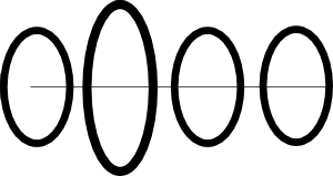
All the Yagi-Uda, Yagi in short, are made of an active element (a dipole in most cases), a reflector (some kind of panel in most cases) and an ensemble of directors (some kind of sticks in most cases). The particularity of the Yagi-Uda array of loops is that this antenna will use loops (again!) for all its elements.
Calculation
I made, it was some time ago when I was living in Sweden, a spreadsheet that help to calculate such antennas. You can visit my new fourre-tout, or download it direct at Antennemulticadres.gnumeric
It was only in French now, but I finaly get some time to translate it in English.
All that is needed is to change the frequency and the number of elements in order to suit your need.
This spreadsheet does not perform gain calculation. The reason is simple: a realistic gain calculation for such an antenna is far too complicated for a spreadsheet. In practice, a 5 elements antenna (an antenna with one reflector, the active element and 3 directors) will be enough in many cases.
Practical realization
No rules here, use your imagination, you are on your own.
Some general considerations: - the elements must be made of some kind of conducting material: copper, aluminum, coaxial cable are best suited. With coaxial cable, we can use only the shield or connect the shield with the inner conductor.
- the horizontal stick can be made of anything and can be placed anywhere, so long than it takes up the various elements. If it is made of conducting material, the elements must be isolated from the stick.
- the distance between the reflector and the active element is very critical. It determine most of the impedance of the antenna as well than other characteristic.
- all the elements are circles, and their center must be on the same line.
Coupling
All we need is some kind of 300 ohms to 75 ohms antenna coupler. Some models are costing less than 1 $.
The active element is coupled to the coupler by its 2 extremity on the 300 ohms symmetrical side of the coupler. Made those connections as short as possible.
The coaxial antenna cable is connected to the other side of the coupler.
Testing
I made one such antenna in Malmö, Sweden. I made it from sticks of wood and pieces of coaxial cable. With a 5 elements antenna, I was able to receive all the TV channels but one that was in black and white with a lot of noise (analog TV). The antenna was calculated for this channel.
After expanding the number of elements to 19, I was able to receive all the channels in color and without noise. This 19 elements was outperforming by 2 dB a wisi EB66, one of the better high gain UHF antenna on the market, that on the frequency the antenna was designed for. I am sure that with a better mechanical design (use of copper instead of coaxial cable), the result would have been even better.
As expected, the gain of the antenna in its 19 elements version was decreasing fast when the channel frequency was decreasing or increasing from the antenna central frequency.
